Summary
The Tail-to-Boom is the connection point between the booms and tail on CUAIR's 2023 twin boom VTOL UAV Atlas.
Documentation
Tail Exploratory Design Review*
Tail Preliminary Design Review (Slides 27-35)
Tail Critical Design Review (Slides 25-42)
Tail to Boom Critical Design Review 2
Tail to Boom Final Design Review (Slides 29 - )
Tail to Boom Machine Documentation
*The entire tail team contributed to the overall shape and basic calculations for the tail
My Role
As a member of the airframe sub-team, I designed, modelled, simulated, physically tested, and implemented the connection point for the tail and the booms on CUAIR's 2023 twin boom aircraft, Atlas.
I ultimately chose the design below because of its simplicity to manufacture and assemble. In the design, there are no loose parts, which eliminates the need to work beneath the plane during assembly and carry around additional parts.
The most important thing I gained from this project was an intuition for how to develop, justify, and test loading conditions on a part but I also learned how to use AVL to analyze the flight characteristics of different wing geometries.
Requirements
Functional Requirements
FR-1: The tail to boom must securely fasten the tail and booms, providing support such that the tail does not detach from the plane under all flight conditions
FR-2: The tail to boom must provide lateral stability such that the tail does not deflect
FR-3: The tail to boom must provide ample access for wiring (and the 2x3 molex header) to run between the boom and tail
Non-Functional Requirements
NFR-1: The tail to boom must be lightweight
NFR-2: The tail to boom must be simple and quick to assemble/disassemble
NFR-3: The tail to boom must be simple to manufacture
Tail Diagram
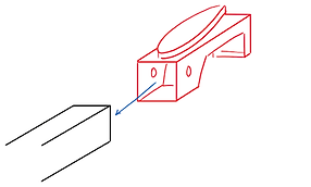
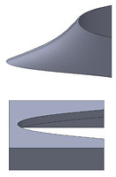
This tail to boom system includes the endrib & wing locks and airflow aid (aero shoe).



Initial Concepts
-
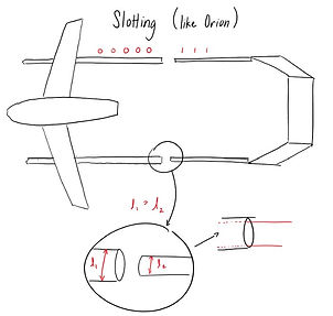
Slotting the tail into the main booms (which would eliminate the tail to boom) - would offer a variety of placement options but would also throw off cg
-
Latches - sturdy but heavy and mounting might be complicated for non-parallel surfaces
-
Sleeve and pin - 3D printing would be complicated, especially with CF Nylon, so for simplicity we decided against it
-
End rib and right angle welding bolt - sturdy but unnecessarily heavy and assembly would still involve getting beneath the bolt to tighten the nuts. However, the idea of an aerodynamic "shoe" to eliminate the hard angle between the square boom and wing would be used.
Calculations
The system could be reasonably modeled by a moment diagram and the forces were obtained using the standard formulas for lift and drag.

AVL
AVL is an aerodynamic analysis program and was used to determine the lift and drag distributions and coefficients for the tail.


Top Model Wing Lock Testing
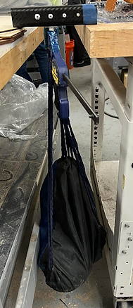
The Top Model website had almost no information so I had to conduct a physical experiment to gauge the strength of the Top Model wing locks.
Test 1 - Axial Force
Conclusion: Wing locks can support ~70 N of axial load before the pin disconnects from the base


Test 2 - Lateral Force
Conclusion: Wing locks alone deflect significantly under relatively small shear loads


Test 3 - Vibration Tolerance
Conclusion: The wing locks will not gradually loosen or separate due to vibrations
Design 1
This was the design presented at the first critical design review. The main feature of this design was the two top model wing locks press-fit into each end rib for easy assembly and disassembly of the tail.
Airflow Aid + Tooling

Endrib + Tooling

Top Model Wing Lock
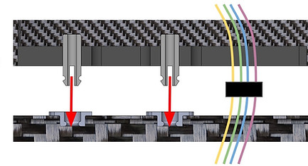
Assembled Cross-Sectional View
Design 2
This was the design presented at the second critical design review. The airflow aid remained almost the same but the end rib and connection to the boom underwent many improvements from.
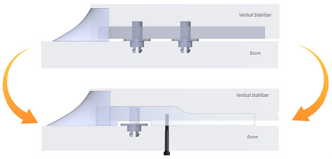
Improvements
-
reduction from two to one wing lock after feedback that it might be difficult to separate
-
to improve ease of disassembly further, a cutout was made around the wing lock to provide access to a tool that operates almost like a reverse plier (see assembly below for image)
-
-
restructuring of the design to sit flush with the boom to provide support for lateral forces following the results of the physical test
-
permanent addition of a bolt and nut to the boom over which the tail to boom slots (does not require threading) over for additional stability
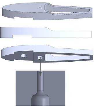
New Endrib


Cost & Mass
(for two sets of tail to boom assemblies as that's how many there will be on the plane)
Total Cost: $10.63
Total Mass: 50.5g


Aerodynamic Shoe and Tooling
Endrib and Tooling
Top Model Wing Lock
Coming Soon
-
Full Integration

