Summary
For the final project for DEA 6210, Architectural Robotics, students were grouped into threes and asked to design an architectural robotic device, furnishing, or system to address a potential issue in future homes.
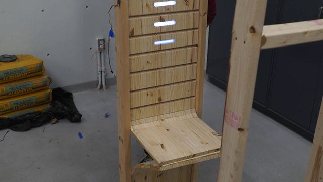
My group designed Axis, an eight-foot-tall reactive wall capable of unfolding into a seat or table at the convenience of the user. This capability makes it an ideal piece to maximize space in narrow hallways or small homes. The main features are listed below:
-
The wall is a custom tambour which was constructed out of several strips of wooden project board and connected by fabric.
-
A series of diffused lights inset into the tambour serve as indicators for the motion of the wall & provide gentle passive lighting for the user.
-
The wall was controlled by a single gesture sensor for ease of use.
My Role
Within my group, my main responsibility was the design and construction of the hardware. To understand the scope and limitations of the materials and size of our project, I spoke with various faculty and developed several prototypes. Once the design was finalized, I used a mixture of CAD and hand-drawing to develop the geometry for the tambour. Finally, I constructed the tambour and frame using a woodshop available to our class.
Despite having previously worked with many of the mediums in this project (everything besides the fabric really), it was still a great challenge because of the unique application of the combination of materials together. Given more time, it is a project I'd love to repeat and improve upon.
(This page focuses entirely upon the hardware but there's more information about the electronics in the final report document)

Before finalizing our design, we decided to use wood for our project because it's familiar. Robotics can feel mechanical and hostile so our goal was to conceal our electronics and mechanisms behind a wooden facade to make our system appear natural and inviting. However, making the wood modular required lots of creative manufacturing.
Material Testing / Prototyping
At first, I intended on using kerfs (partial-depth lengthwise cuts in the wood) to make the boards bendable. After some experimentation, I found that although decently flexible, the kerfed boards couldn't sustain compressive loads, especially since repeated bending weakened the fibers.

Various Samples of Kerfed Hardwood & Plywood
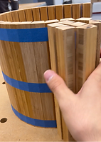
By the suggestion of a faculty member in the design studio, I decided to investigate tambour* as an alternative to kerfs. Using a prototype to test the concept [right], I discovered that tambour is surprisingly robust, and can bear impressive loads when adjacent edges are in full contact. Through this prototype I also realized the potential for designing our own geometry to hard code functionality into the tambour itself.
Later on I'd realize that even with fabric glue and staples, the tambour has a tendency to peel apart near the edges of the wood, so it's difficult to make the tambour move precisely and predictably. Despite it still working for the most part, I'd choose a lighter weight material for the tambour and heavier duty glue to adhere the fabric to the wood if I did this project again.
*Tambour is many strips of wood arranged side by side and adhered to a fabric backing [left]. The fabric permits rotation along the axis of the strip at each intersection, leading to designs such as the sliding cabinet drawer below [center].


Design
Based on the discoveries from my prototype, we decided to continue with the tambour and had the idea of creating a wall that slides on a rail system and is capable of unfurling into a seat or table. Ideally, the tambour would be housed within a wall and lie flush with the surrounding walls, but we decided to construct a dedicated frame since it'd be more convenient to integrate and present. The frame had a channel routed out so the tambour could the frame itself as the rail system rather than needing to manufacture additional pieces.
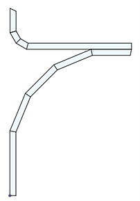
I went through a similar design process for the tambour [left] and frame that would ultimately house the tambour [right]
1. Sketch the model in CAD (I used Fusion 360) using rough dimensions for the wall


2. Note the dimensions and angles for each cut


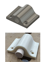
3D printed pieces which housed 1/2" dowels were screwed into both sides of the tambour. These additions allowed the tambour to slide within the a channel routed into one side of the 2'x4' frame.
Sadly, there was lots of friction from the wood-wood contact. I assumed that since the system would be mostly vertical, the substantial tolerances would be enough to eliminate most of the friction. However, the opposite was true. The tolerance in the width of the channel and spacing around the tambour allowed for twisting in unexpected directions, which caused the system to snag and stutter. In the future, I'd like to investigate modifying a COTS rail system to accommodate the tambour or designing a separate rail system out of aluminum for reduced friction.


